| Oracle® Communications OC-CNE Installation Guide Release 1.0 F16979-01 |
|

 Previous |
 Next |
Goals
Background and strategic fit
Requirements
User Interaction and Design
CNE Overview
CNE Frame Overview
Problem Statement
CNE Installation Preparation
CNE Installation - Setup the Management Server and Switches
Setup the Switches
Configure the Enclosure Access
Configure the OA EBIPA
Configure the Enclosure Switches
Engage Customer Downlinks to Frame
Install OceanSpray Tools
Configure site specific details in configuration files
Perform Host OS installations
Servers Install Host OS
Package Update
Servers do a Yum update
Harden the OS
Install VMs as Needed
Create the Guests
Install the Guest OS
Install MySQL
Install Kubernetes on CNE Nodes
Servers Reach Out to Repos and Install Software
Configure Common Services on CNE Cluster
Helm Pulls Needed Items from Repositories
This section walks through expected installation steps for the CNE given the selected software delivery model.
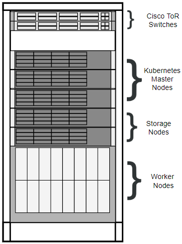
Figure B-2 Frame reference
A solution is needed to initialize the frame with an OS, a Kubernetes cluster, and a set of common services for 5G NFs to be deployed into. How the frame is brought from manufacturing default state to configured and operational state is the topic of this page.
Manufacturing Default State characteristics/assumptions:
Frame components are "racked and stacked", with power and network connections in place
Frame ToR switches are not connected to the customer network until they are configured (alternatively, the links can be disabled from the customer side)
An installer is on-site
An installer has a notebook and a USB flash drive with which to configure at the first server in the frame
An installer's notebook has access to the repositories setup by the customer
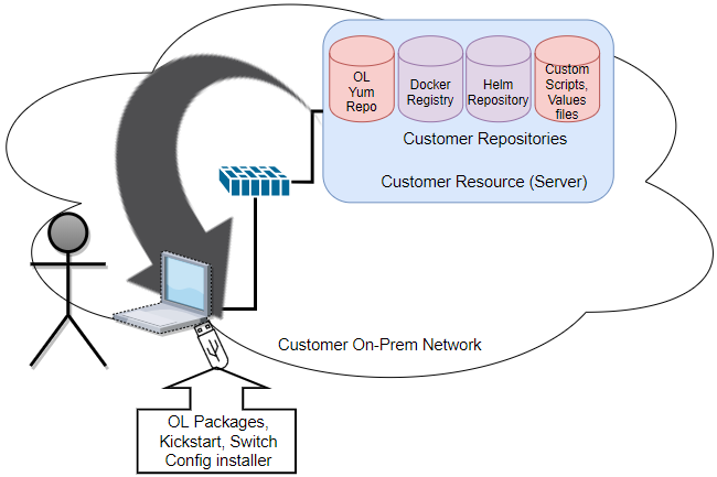
Setting up the Notebook
Figure B-3 Setup the Notebook and USB Flash Drive
Install OS on a "Bootstrap" Server
The 1st RMS in the frame will be temporarily used as a bootstrap server, whereby a manual method of initial OS install will be applied to start a "standard" process for installing the frame. The activity performed by this "bootstrap" server should be minimized to get to a standard "in-frame configuration platform" as soon as possible. The bootstrap server should be re-paved to an "official" configuration as soon as possible. This means the "bootstrap" server will facilitate the configuration of the ToR switches, and the configuration of a Management VM. Once these two items have been completed, and the management VM is accessible from outside the frame, the "bootstrap" server will have fulfilled its purpose and can then be re-paved.
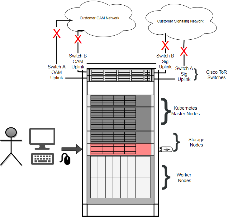
The figure below is very busy with information. Here are the key takeaways:
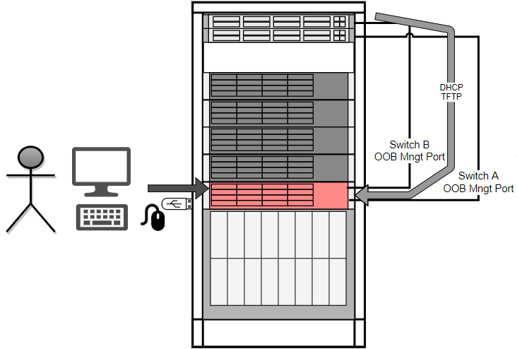
Figure B-4 Setup the Management Server
Setup Switch Configuration Services
Configure DHCP, tftp, and network interfaces to support ToR switch configuration activities. For the initial effort of CNE 1.0, this process is expected to be manual, without the need for files to be delivered to the field. Reference configuration files will be made available through documentation. If any files are needed from internet sources, they will be claimed as a dependency in the customer repositories and will be delivered by USB to the bootstrap server, similar to the OL iso.
Figure B-5 Management Server Unique Connections
Using the Enclosure Insight Display, configure an IP address for the enclosure.
From the management server, use an automated method, manual procedure, or configuration file to push configuration to the OA, in particular, the EBIPA information for the Compute and IO Bays' management interfaces.
Figure B-6 Configure OAs
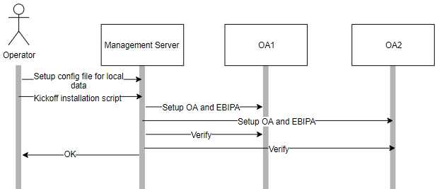
Figure B-7 Configure the Enc. Switches
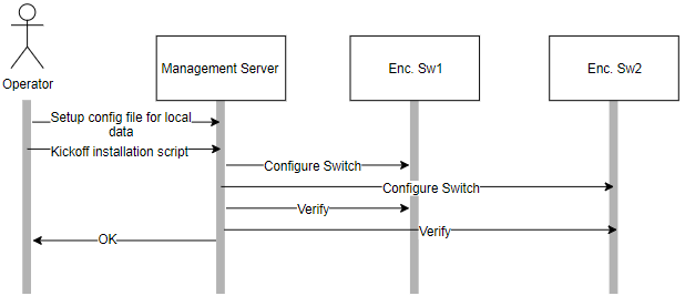
At this point, the management server and switches are configured and can be joined to the customer network. Enable the customer uplinks.
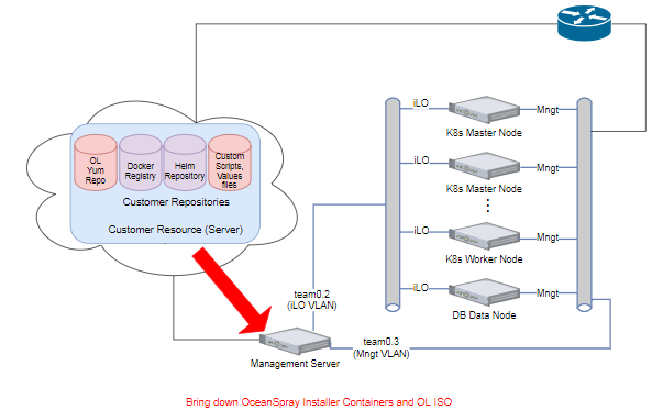
Setup Installation Tools
With all frame networking assets (ToR and Enclosure switches) configured and online, the rest of the frame can be setup from the management server.
Figure B-8 OceanSpray Download Path
Where appropriate, update configuration files with site specific data (hosts.ini, config maps, etc).
Install the Host OS on All Compute Nodes
Run Host OS Provisioner against all compute nodes (Master nodes, worker nodes, DB nodes).
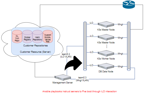
Ansible Interacts with Server iLOs to perform PXe boot
Figure B-9 Install OS on CNE Nodes - Server boot instruction
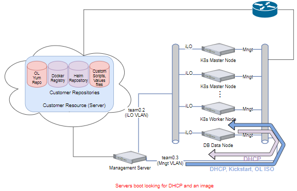
Servers boot by sending DHCP request out available NIC list. The broadcasts out the 10GE NICs are answered by the management server host OS provisioner setup. The management server provides the DHCP address, a boot loader, kickstart file and an OL ISO via NFS (a change in a future release should move this operation to HTTP).
Figure B-10 Install OS on CNE Nodes - Server boot process
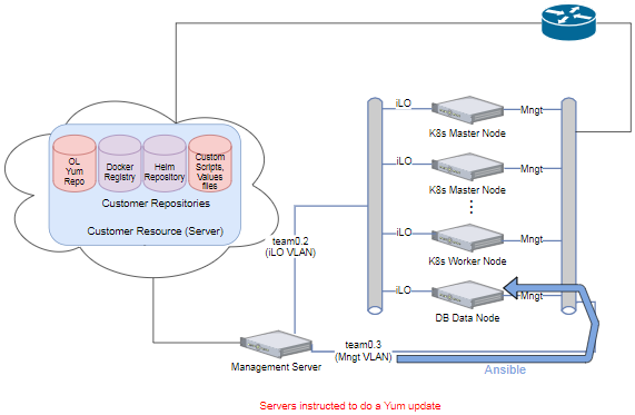
At this point, server's host OS is installed, hopefully from the latest OL release. If this was done from a released ISO, then this step involves updating to the latest Errata. If the previous step already involved grabbing the latest package offering, then this step is already taken care of.
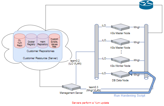
Ansible triggers servers to do a Yum update
Figure B-11 Update OS on CNE Nodes - Ansible
Up to this point, the host OS management network could have been a private network without access to the outside world. At this point, the servers have to reach out to the defined repositories to access the Yum repository. Implementation can choose to either provide public addresses on the host OS instances, or a NAT function can be employed on the routers to hide the host OS network topology. If a NAT is used, it is expected to be a 1 to n NAT, rather than a 1 to 1. Further, ACLs can be added to prevent any other type of communication in or out of the frame on this network.
Figure B-12 Update OS on CNE Nodes - Yum pull
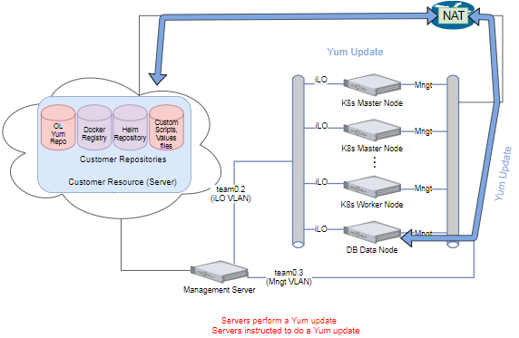
Figure B-13 Harden the OS
Some hosts in the CNE solution are to have VMs to address certain functionality, such as the DB service. The management server has a dual role of hosting the configuration aspects as well as hosting a DB data node VM. The K8s master nodes are to host a DB management node VM. This section shows the installation process for this activity.
Figure B-14 Create the Guest

Following a similar process to sections 2.5.1-2.5.3, the VM OS is installed, updated, and hardened. The details of how this is done is slightly different than the host OS, as an iLO connection is not necessary; however, they are similar enough that they won't be detailed here.
Execute Ansible Playbooks from DB Installer Container
Show simple picture of Ansible touching the DB nodes.
Customize Configuration Files
If needed, customize site-specific or deployment specific files.
Run Kubespray Installer
For each master and worker node, install the cluster.
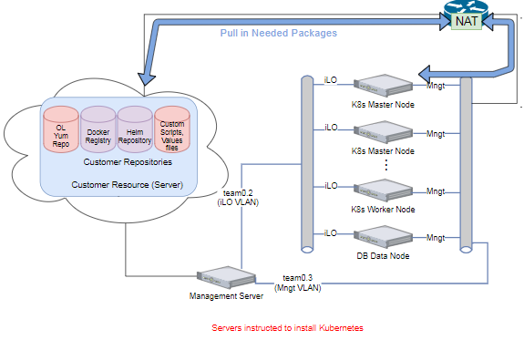
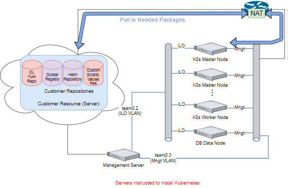
Ansible/Kubespray Reaches Out to Servers to Perform Install
Figure B-15 Install the Cluster on CNE Nodes
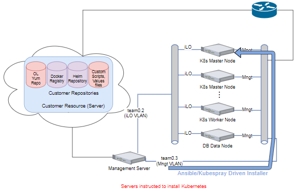
Figure B-16 Install the Cluster on CNE Nodes - Pull in Software
Customize Site or Deployment Specific Files
If needed, customize site or deployment specific files, such as values files.
Run Configurator on Kubernetes Nodes
Install the Common Services using Helm install playbooks. Kubernetes will ensure appropriate distribution of all Common Services in the cluster.
Figure B-17 Execute Helm on Master Node
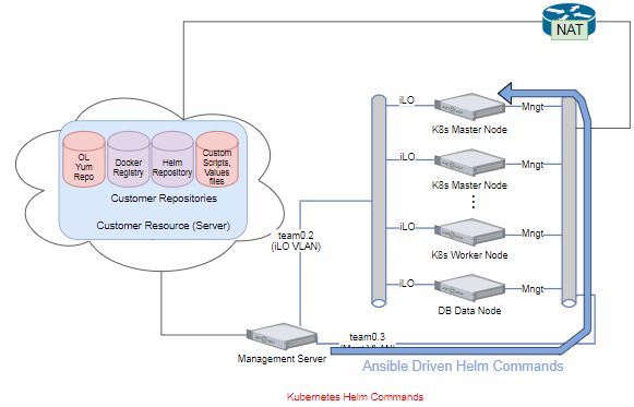
Figure B-18 Master Node Pulls from Repositories